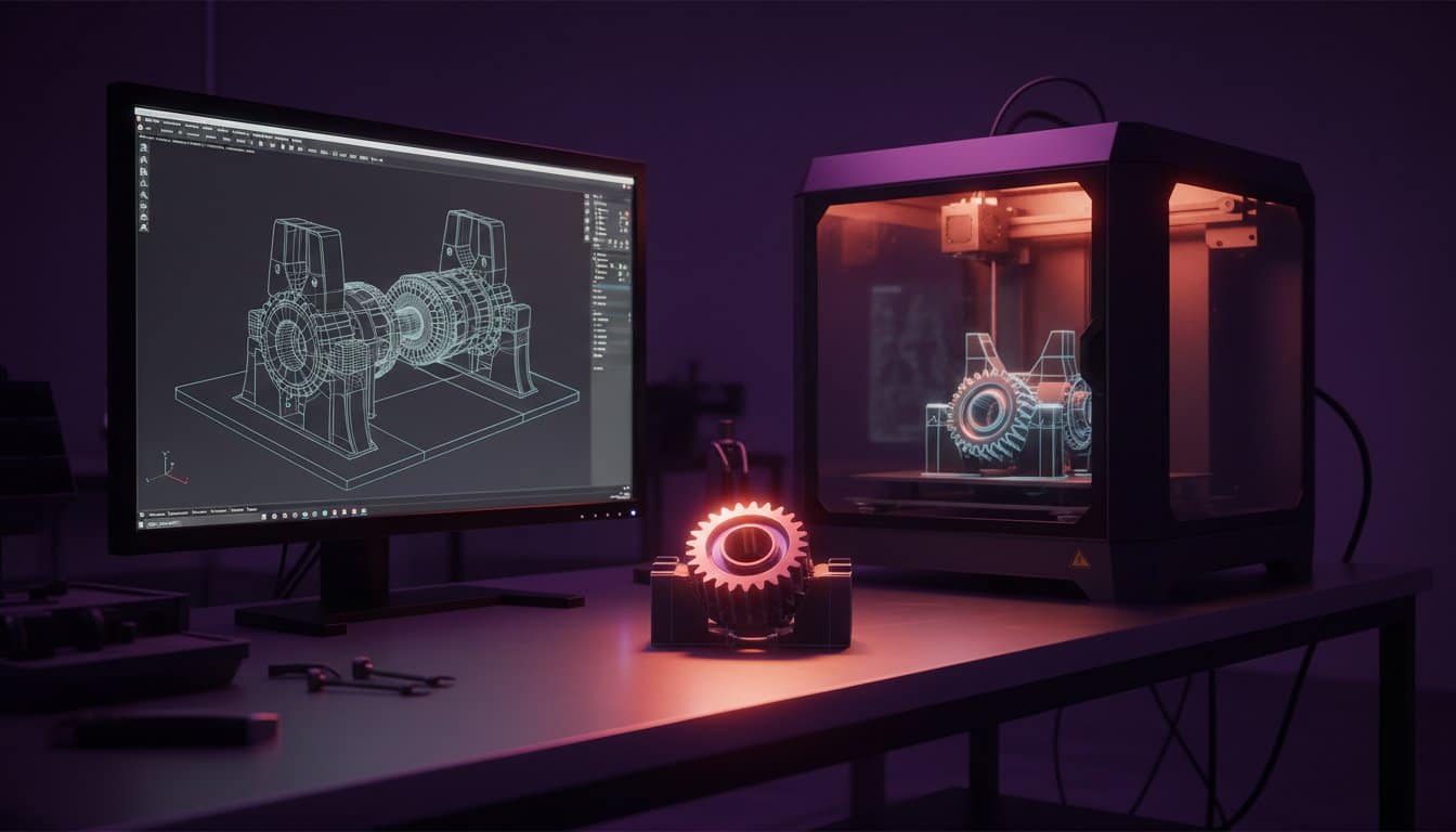
A model that looks flawless on your monitor is often a liability the moment it hits the build plate. You’ve likely felt the frustration of finding a pile of wasted filament after a 12-hour print because of a geometry error or an overlooked tolerance. At Protomolecule, we see these setbacks daily; in fact, industry data suggests that 40% of additive manufacturing failures stem from design flaws rather than hardware issues. Mastering 3d design for 3d printer applications is the only way to eliminate this waste and maintain your project’s momentum.
We agree that your time is too valuable for trial and error. This professional engineering guide delivers the exact Design-for-Additive-Manufacturing (DfAM) rules you need to create precision parts that function perfectly the first time. You’ll learn how to produce watertight models, calculate accurate tolerances for moving assemblies, and select the CAD software that fits your specific engineering workflow. Stop guessing and start building with the technical confidence of a professional studio. We’re moving from basic shapes to industrial-grade components to ensure you beat the clock on your next production run.
Key Takeaways
- Master the critical distinction between aesthetic CG modeling and engineering-grade CAD to ensure your digital volumes are always manifold and watertight.
- Identify the most effective industrial software for 3d design for 3d printer success, focusing on tools that export high-fidelity STL and STEP files.
- Implement a professional engineering workflow, starting with digital caliper measurements and constrained 2D sketches to guarantee high-precision physical parts.
- Apply essential Design for Additive Manufacturing (DfAM) rules to eliminate structural failures and ensure your complex geometries print perfectly every time.
- Learn when to scale beyond desktop limitations by leveraging professional rapid prototyping for functional testing with zero compromise on quality.
The Fundamentals of 3D Design for 3D Printing
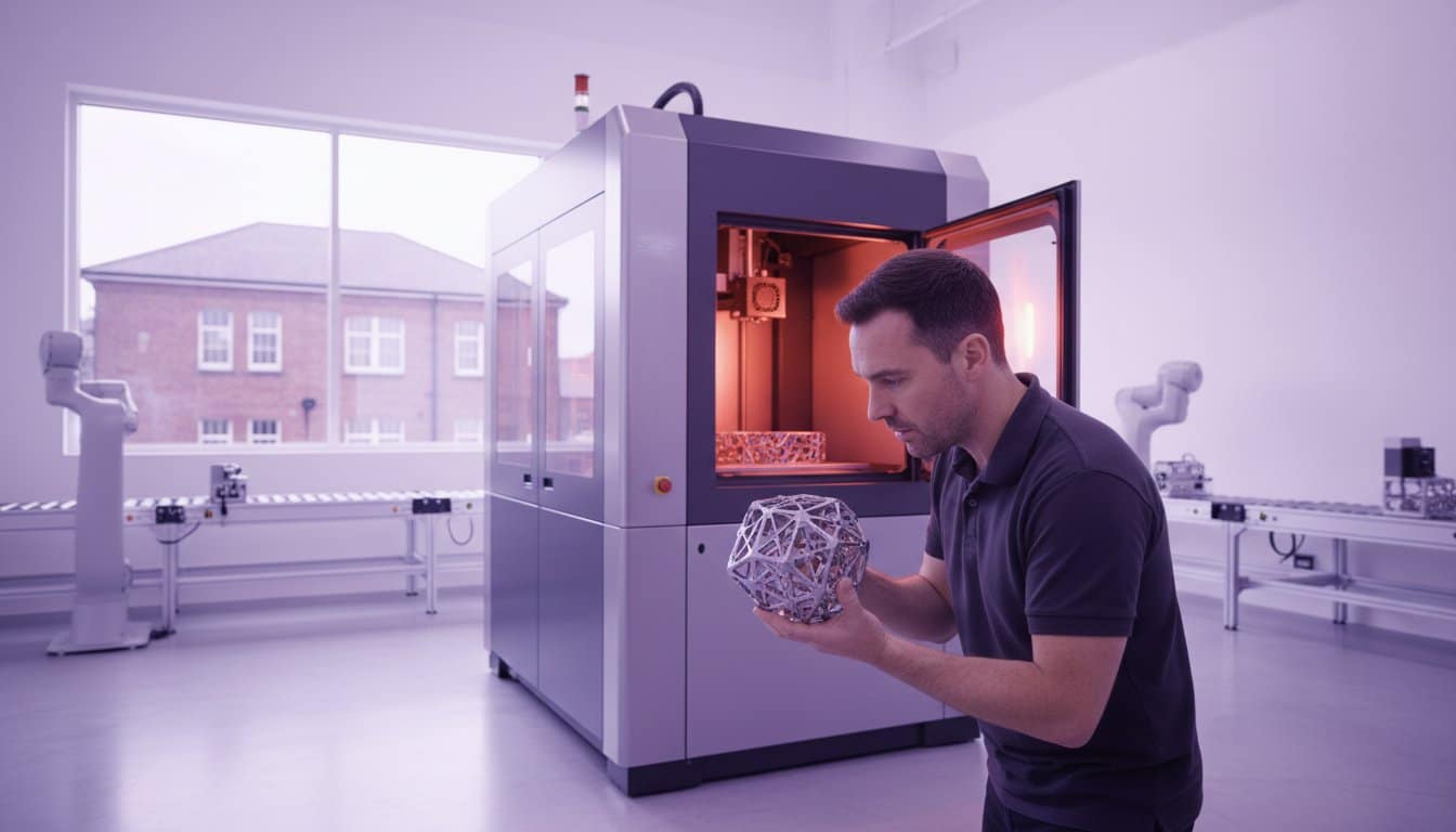
Mastering 3d design for 3d printer success requires a fundamental shift from visual aesthetics to geometric integrity. You aren’t just drawing a shape; you’re engineering a manifold volume that exists in physical space. Professional results depend on creating digital files that a slicer can interpret without ambiguity. Precision starts at the digital level. While computer graphics (CG) focus on surface aesthetics for films or games, engineering-grade CAD (Computer-Aided Design) defines the physical reality of a part. CG models often rely on “smoke and mirrors” like textures and hollow shells, but manufacturing requires solid, calculated volumes.
The STL file remains the industry standard bridge between your design software and the hardware. Developed in 1987, this format translates complex curves into a mesh of triangles. It’s the universal language for 3D printing systems worldwide. To ensure your part translates correctly, every edge in your design must share exactly two faces. This is the definition of manifold geometry. If an edge connects to only one face, the model has a “hole” in its logic, leading to failed prints and wasted material. Protomolecule eliminates these errors through rigorous file validation, ensuring your project moves from screen to reality without delay.
Solid vs. Mesh Modelling: Which Should You Choose?
Parametric or Solid modelling is the backbone of functional engineering. Using formats like STEP or IGES, this method defines geometry through mathematical relationships. It’s the superior choice for mechanical adjustments and reverse engineering because it allows for precise dimensional edits. If a bolt hole needs to move by 2mm, solid modelling makes that change instant and accurate. In contrast, Mesh or Polygon modelling excels at organic, artistic shapes. While mesh files are harder to modify for mechanical fit, they’re essential for sculptures or complex ergonomics where mathematical constraints would be too restrictive.
Understanding the “Watertight” Requirement
Visualise your 3D model as a physical container. If you filled the digital volume with water, would any leak out? A “watertight” model is a fully enclosed volume with no gaps in its surface. Common pitfalls that ruin print jobs include flipped normals, where the software confuses the “inside” and “outside” of a face, and internal stray faces that confuse the slicer’s pathing. These errors often lead to “ghost” layers or missing sections in the final part. Manifold geometry is the essential state where every edge joins exactly two faces to form a continuous, enclosed surface. Don’t let poor file preparation slow your production down. Our team at Protomolecule maintains a 24-hour turnaround for urgent prototypes, ensuring zero compromise on quality for every Nottingham and UK-wide client.
Selecting the Right 3D Design Software
Your software choice determines whether your project succeeds or stalls at the printer. Effective 3d design for 3d printer workflows depend on matching user intent with technical capability. Professional engineers categorise software into three distinct streams: hobbyist, artistic, or industrial engineering. Each serves a specific purpose in the development cycle. High-fidelity exports are non-negotiable; you must choose software that generates clean STL or STEP files to avoid geometry errors. Adhering to Design for Additive Manufacturing (DfAM) principles ensures your digital models translate into functional physical parts without structural failure.
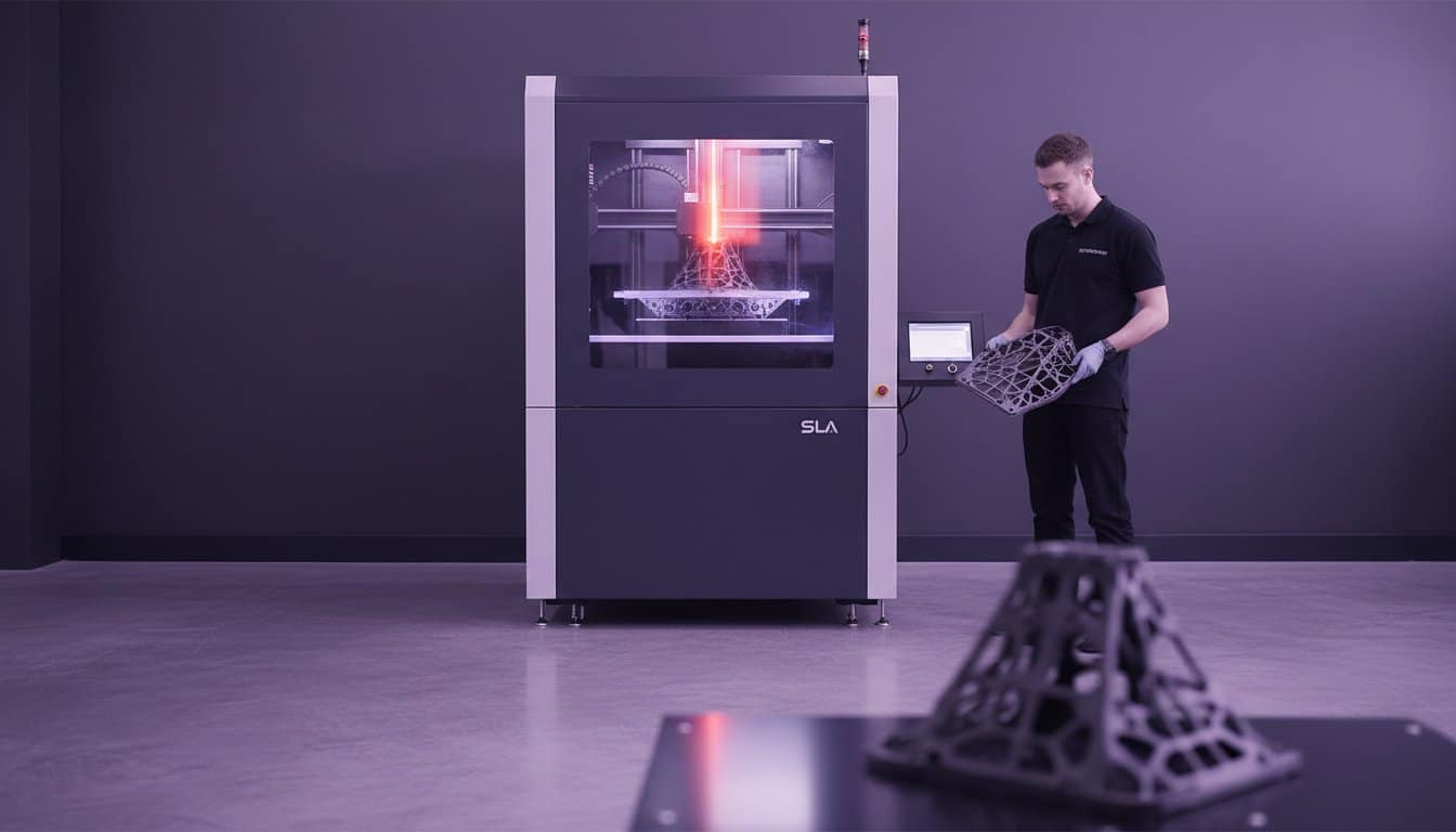
Professional studios rarely rely on a single program. They use a stack of tools to balance speed and precision. You might use one tool for rapid conceptualisation and another for final tolerance adjustments. This multi-tool approach prevents technical bottlenecks. Selecting the right tool early reduces the learning curve and accelerates your path to a physical prototype. If your project requires industrial-grade speed, consider our rapid prototyping services to validate your designs within 24 hours.
Beginner-Friendly Tools for Quick Concepts
Tinkercad provides the most efficient browser-based entry point. It uses basic geometric primitives to build complex shapes quickly. It’s ideal for simple brackets or spacers where aesthetic refinement is secondary to speed. SketchUp offers a familiar interface for architectural 3D printing; however, it often creates non-manifold “mesh” errors. These “leaky” models can add 20 minutes of repair time in the slicer. 3D Slash uses a unique, block-based approach. It’s perfect for non-designers who need to visualise a concept without learning traditional CAD coordinates.
Professional and Industrial CAD Suites
Fusion 360 is the current industry standard for 3d design and parametric control. It allows you to revisit the design history to change a single dimension, which automatically updates the entire model. This is essential for precision engineering. Blender is the powerhouse for organic textures and complex mesh manipulation. It excels where CAD software struggles, such as ergonomic grips or artistic enclosures. For those who prefer logic-based modelling, FreeCAD and OpenSCAD provide open-source alternatives. OpenSCAD uses code-driven parameters, making it the most reliable choice for technical parts that require infinite variations based on mathematical inputs. 3d design for 3d printer success starts with these robust platforms, ensuring zero compromise on quality from the first layer to the last.
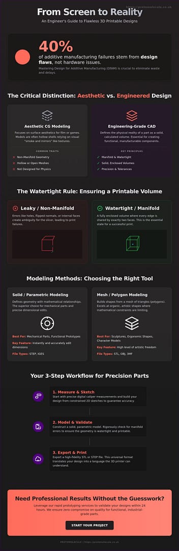
Step-by-Step: Your Workflow for a Printable Design
Precision in 3d design for 3d printer workflows begins with physical data. Grab your digital calipers and capture every critical dimension before you even open your CAD software. A single millimetre error at this stage can waste a 24-hour print cycle. Once you have your data, create a 2D profile. You must “fully constrain” every line and arc. This locks the geometry in place, preventing accidental shifts when you modify related features later. Protomolecule’s engineers use this rigorous approach to ensure that parts like passenger train seat arms or custom automotive components fit perfectly the first time.
After the sketch is locked, execute the “Extrude” or “Revolve” command to create your 3D solid. Success here relies on following established Design for Additive Manufacturing (DfAM) principles. These rules ensure your geometry is actually printable without unnecessary failure. Apply “Fillets” and “Chamfers” to every internal corner. These features aren’t just for aesthetics; they redistribute stress and significantly improve part durability. Sharp internal 90-degree angles are structural failure points. By adding a 2mm fillet, you can increase the part’s load-bearing capacity by up to 30% depending on the material used.
From Sketch to Solid Body
Professional workflows use boolean operations, such as Union, Difference, and Intersection, to build complex assemblies from simple primitives. Always design your part in its intended print orientation. This strategy reduces the need for support structures and improves surface finish on critical faces. If you’re designing for 3D printing services, this foresight directly translates to faster lead times and lower costs. Don’t let poor orientation slow your project down; plan for the build plate from the first sketch.
Exporting for the Slicer: STL vs. STEP
Choosing the right file format is vital for precision. STL files use a mesh of triangles. If the resolution is too low, your curves will suffer from “faceting,” resulting in a blocky finish. Set your “Deviation Tolerance” to 0.01mm to find the perfect balance between detail and file size. For high-precision engineering projects, we recommend exporting as a STEP file. Unlike STL, STEP files retain true mathematical curves, which is essential when using our 3D printing services for industrial components. If you’re working with complex existing objects, 3D scanning provides a rapid shortcut. It allows you to build your 3d design for 3d printer directly around a high-fidelity digital twin of a physical object. Zero compromise on quality is the Protomolecule standard, and your export settings must reflect that level of detail.
Design for Additive Manufacturing (DfAM) Rules
Stop asking why your parts break or arrive with messy surface finishes. Most 3D printing failures don’t stem from the machine; they start on your screen. Design for Additive Manufacturing (DfAM) is the professional framework used to prevent these errors before the first layer even starts. If you ignore these constraints, you’re essentially designing for failure. Effective 3d design for 3d printer success requires a “Zero Compromise” approach. This means you must tailor every fillet, wall, and hole to the specific mechanical strengths of your chosen process, whether that’s FDM or SLA.
Material choice dictates your geometry. PLA is incredibly rigid but snaps under sudden impact. PETG offers better chemical resistance and flexibility but strings easily if your retraction paths aren’t optimized. Resin (SLA) provides unmatched detail but requires internal venting for hollow parts to avoid “suction cupping” during the build. Don’t let technical oversights slow your project down. Match your geometry to your material properties to ensure your part performs in the real world.
Overhangs, Bridges, and the 45-Degree Rule
Gravity is the primary enemy of a successful print. The 45-degree rule is your baseline safety margin. Any angle steeper than 45 degrees relative to the build plate usually requires support structures. These supports increase material waste and leave scars that require manual post-processing. Design self-supporting geometry by using chamfers instead of rounds on overhanging edges. Bridging allows a printer to extrude plastic across a gap between two points. Most industrial FDM printers comfortably bridge gaps of 5mm to 10mm without sagging, but exceeding this requires internal support or clever geometry changes to maintain structural integrity.
Wall Thickness and Tolerances
Precision is non-negotiable. For functional FDM parts, 1.2mm is the reliable floor for minimum wall thickness. This allows for three shells with a standard 0.4mm nozzle, providing the necessary skin strength to handle mechanical stress. When you’re designing interlocking components, you must account for “Fit” by adding a 0.2mm to 0.5mm clearance between mating surfaces. Without this gap, thermal expansion and layer inconsistencies will fuse your parts together.
Holes require special attention because they almost always shrink during the cooling process. Professional engineers know that “3D printed holes are hexagonal approximations that contract inward, so always oversize your diameters by 0.1mm to 0.2mm to achieve a true functional fit.” Use these rules to beat the clock and get your prototypes right the first time.
Ready to move from digital concept to physical reality? Get a quote today and let our engineering team handle the precision manufacturing for you.
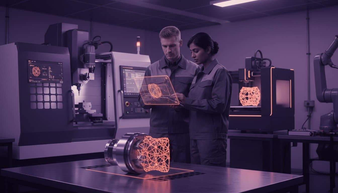
Scaling Up: From Desktop Design to Industrial Production
Desktop printers serve a vital purpose for basic proof-of-concept. However, they hit a hard limit when you require industrial precision or complex geometries that demand structural integrity. When your 3d design for 3d printer moves from a hobbyist project to a functional engineering component, desktop tolerances often fail to meet the ±0.1mm standard required for high-performance mechanical assemblies. Moving to professional rapid prototyping allows you to test with engineering-grade resins and carbon-filled filaments that standard machines cannot handle. Transitioning to batch production ensures your product is ready for the commercial market with consistent quality across 10 or 1,000 units.
The Value of Professional Design Optimization
Professional optimization bridges the gap between a digital model and a cost-effective physical product. We focus on lightweighting through lattice structures, which can reduce part weight by up to 60% while maintaining required strength. This directly lowers material costs and machine time. Part consolidation is another key strategy. We’ve redesigned assemblies that previously required ten separate components into a single, complex part. This eliminates assembly labor and removes potential failure points. Protomolecule’s expertise turns “impossible” geometries into manufacturable reality, ensuring your 3d design for 3d printer is optimized for the specific physics of industrial additive manufacturing.
Getting Your Project Manufactured Fast
Speed is critical in modern product development. We provide a 24-hour turnaround for most projects because we understand that delays cost money. To achieve this, your file must be “clean” for our automated systems to provide an instant quote. A clean file prevents manual repair time and moves your project straight to the print bed. Before uploading, run through this final checklist:
- Manifold Geometry: Ensure your mesh is “water-tight” with no holes or self-intersecting faces.
- Correct Tolerances: Account for material shrinkage, usually 0.2% to 2% depending on the polymer chosen.
- Optimized Orientation: Design with the print bed in mind to minimize support structures and surface scarring.
Don’t let slow lead times stall your innovation. Beat the clock and get your components in hand by tomorrow. We maintain zero compromise on quality, whether we are producing 80s JDM wheel centre caps or passenger train seat arms. Ready to see your design in the real world? Get an instant quote today.
Accelerate Your Engineering Workflow Today
Mastering 3d design for 3d printer success requires a strategic shift from aesthetic CAD to functional, additive-ready geometry. You’ve explored the essential DfAM rules that prevent structural failure and learned how to scale designs from desktop concepts to industrial production. Success hinges on precise tolerances and selecting the right material for specific mechanical loads. Don’t let design complexities or software limitations stall your progress.
Protomolecule removes the friction between your digital model and a finished industrial component. We deliver a 24-hour rapid prototyping turnaround to ensure you beat the clock on every project. Our facility utilizes industrial-grade FDM, SLA, and SLS technologies to handle everything from intricate prototypes to robust, end-use parts. If your geometry presents technical challenges, our expert engineering support is ready to optimize your complex parts for maximum performance. We focus on results so you can focus on innovation.
Take the next step in your manufacturing journey. Turn your complex designs into precision parts with Protomolecule and see your engineering vision come to life with zero compromise on quality. Your next breakthrough is just one print away.
Frequently Asked Questions
What is the best 3D design software for 3D printing beginners?
Autodesk Fusion is the top choice for beginners who want professional results. It’s an industry-standard tool that combines parametric modelling with an intuitive interface. Over 1.2 million active users rely on its capabilities for precision engineering. While Tinkercad offers a basic entry point for simple shapes, Fusion allows you to master 3d design for 3d printer workflows that scale with your project’s complexity. It’s the most reliable way to turn concepts into functional parts.
How do I make my 3D design “watertight” for printing?
You make a design watertight by ensuring the mesh is manifold with zero holes or self-intersecting faces. Every edge in your model must connect to exactly two faces to form a continuous surface. A 2023 industry study found that 40% of print failures stem from non-manifold geometry that confuses the slicing software. Use the “Check Mesh” or “Repair” tools in your CAD software to automatically close gaps. If your volume isn’t fully enclosed, the printer won’t calculate infill correctly.
Why does my 3D design look different in the slicer than in CAD?
This visual difference occurs because CAD software uses mathematical curves while slicers require a triangulated mesh. When you export an STL file, the software converts smooth surfaces into thousands of tiny triangles. If your chordal tolerance is set too high, a smooth 50mm sphere will look like a jagged polygon. Adjust your export settings to a 0.01mm deviation to maintain high-performance accuracy. Precision in the digital file is the only way to ensure zero compromise on the final physical quality.
Can I use a 2D image to create a 3D design for a 3D printer?
You can create a 3D design from a 2D image by converting it into an SVG vector file for extrusion. This is a lightning-fast method for producing custom logos or 80s JDM wheel centre caps. Simply import the vector into your workspace and pull the flat shape into a 3D volume. While a standard JPEG requires manual tracing, an SVG conversion takes less than 300 seconds in modern software. This technique is a core part of 3d design for 3d printer projects involving branding.
What are the most common mistakes in 3D design for manufacturing?
The most common mistakes are insufficient wall thickness and failing to account for material shrinkage. You should maintain a minimum wall thickness of 1.2mm for FDM parts to ensure they don’t snap under stress. Data shows that 30% of design failures happen because engineers forget to add fillets to internal corners, which creates weak points. Always design with the specific manufacturing process in mind. Avoiding these errors helps you beat the clock and move straight to batch production.
Do I need to design support structures myself in the CAD software?
You don’t usually need to design supports manually because modern slicing software handles this automatically. Slicers like Cura or PrusaSlicer generate these sacrificial structures in seconds based on your overhang angles. However, for complex industrial projects like passenger train seat arms, manual supports can reduce material waste by 15%. Use manual placement only when you need to protect a critical surface finish or a specific tolerance that auto-generation might compromise. For most jobs, let the slicer do the work.
How do I calculate the correct tolerances for interlocking 3D printed parts?
Apply a 0.2mm offset between mating surfaces for a reliable functional fit. If you need a tight press-fit, reduce this gap to 0.1mm, while a 0.3mm clearance is better for parts that must move or rotate freely. Research indicates that 95% of FDM printers in the UK achieve consistent results using these specific offsets. Don’t guess your dimensions during the design phase. Using these proven tolerances ensures your assemblies fit perfectly the first time, preventing costly delays and reprints.