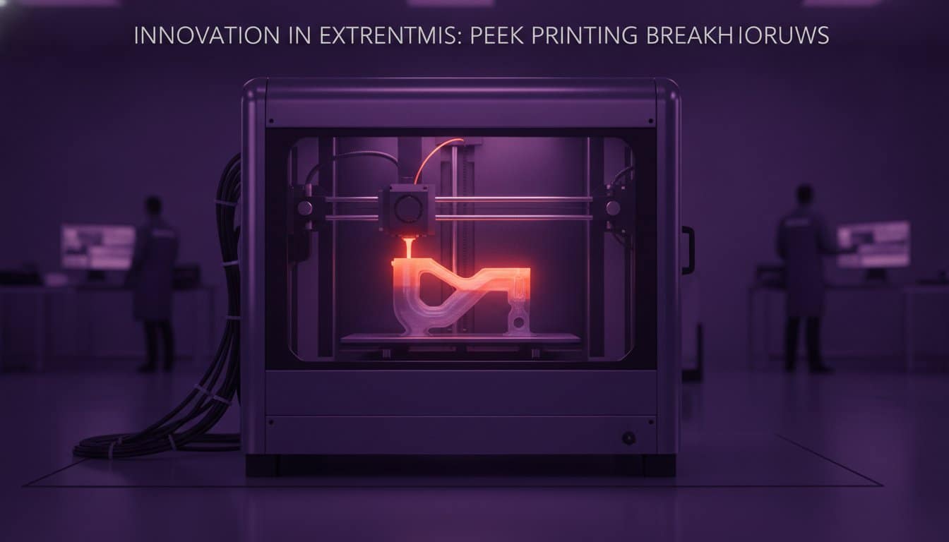

The “magic button” for instant file conversion remains a persistent myth in the engineering world; professional results require a strategic reconstruction of design intent rather than a simple software click. Learning how to create a cad model from a scan is not about finding a shortcut. It’s about mastering a rigorous reverse engineering workflow that prioritises precision over speed. You have likely experienced the frustration of opening an “auto-converted” STL only to find a messy, uneditable mesh that fails every tolerance check. It is a common bottleneck that stalls production and compromises project deadlines.
This guide provides the technical roadmap to transform raw scan data into precise, manufacture-ready CAD models that align with the latest BS 8888:2025 standards. We will examine the exact steps required to bridge the gap between mesh and parametric geometry. You’ll learn to produce clean STEP or IGES files that are fully editable and ready for the factory floor, ensuring your workflow is as efficient as it is accurate. Stop settling for broken surfaces and start delivering industrial-grade results.
Key Takeaways
- Distinguish between “dumb” mesh data and parametric geometry to ensure your models are fully editable for future engineering changes.
- Master the essential workflow of how to create a cad model from a scan by prioritising data preparation and precise coordinate alignment.
- Utilise deviation analysis to compare your reconstructed CAD against raw scan data, guaranteeing uncompromising dimensional accuracy.
- Optimise your final STEP or IGES files for specific UK manufacturing processes by applying professional tolerance management techniques.
- Align your reverse engineering projects with BS 8888:2025 standards to ensure seamless integration with industrial production lines.
Understanding the Data: From Mesh Clouds to Parametric CAD
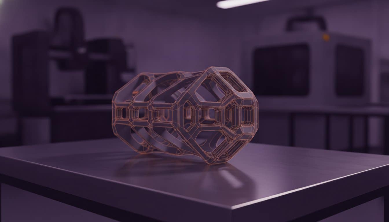
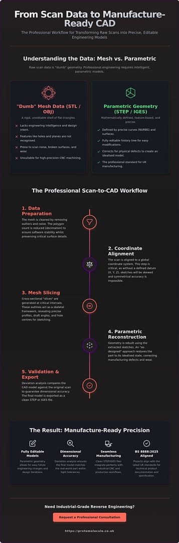
Raw data from a 3D scanning process usually arrives as a point cloud or a triangle mesh. These files, typically in STL, OBJ, or PLY formats, consist of millions of tiny facets that describe the surface of an object. To a computer, this is “dumb” data. It lacks the mathematical intelligence required for engineering because individual features like holes, planes, and fillets aren’t recognised as distinct entities. You can’t simply click a hole in an STL and change its diameter; the software only sees a collection of triangles.
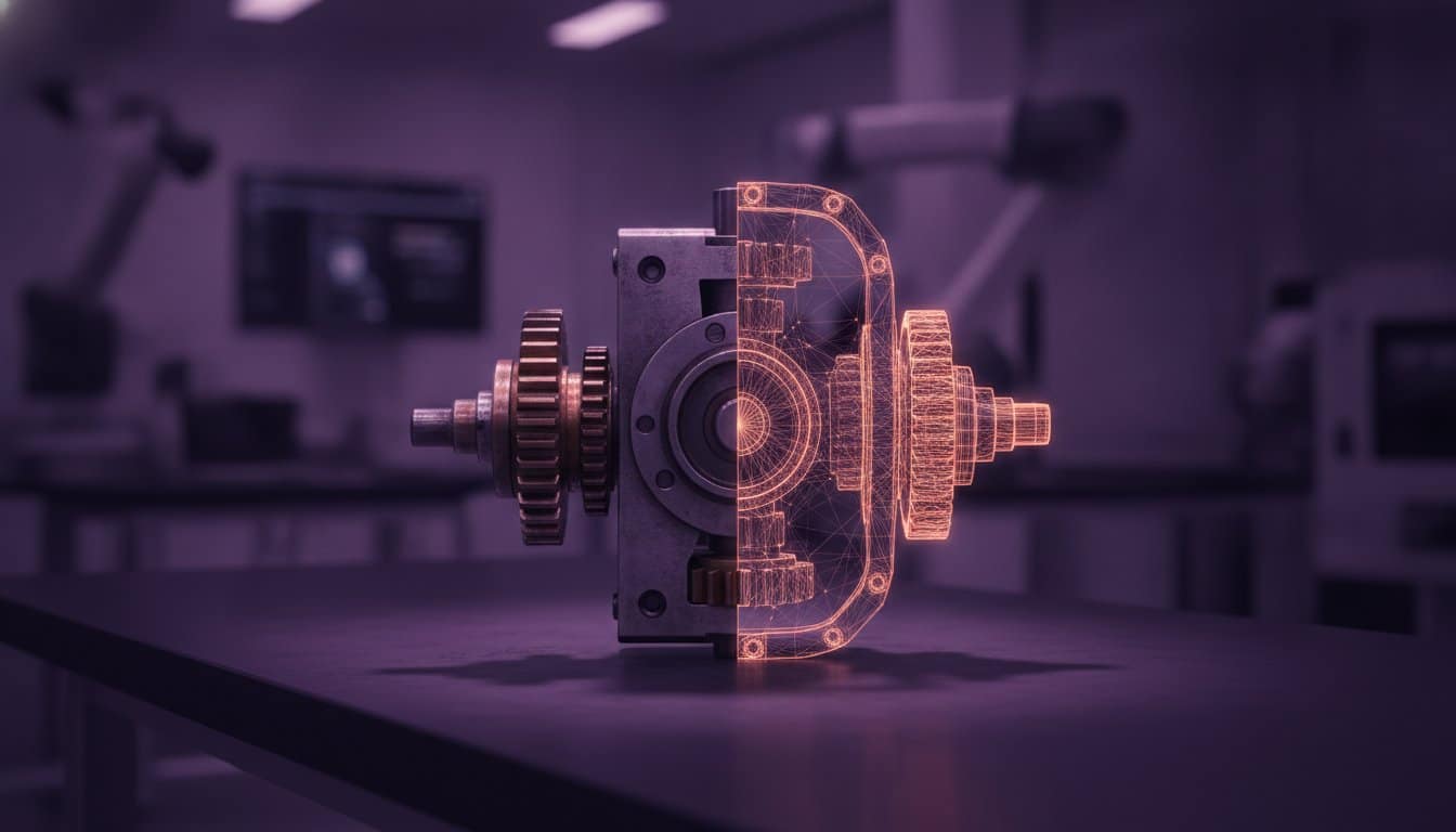
Understanding how to create a cad model from a scan requires shifting from these polygons to parametric geometry. Professional engineering relies on Non-Uniform Rational B-Splines (NURBS), which are the mathematical foundation of STEP and IGES files. Unlike a mesh, parametric CAD is feature-based. It allows you to define design intent. This is the process of reconstructing a part based on how it was originally intended to function, rather than just how it exists as a worn or warped physical object.
The Difference Between STL and STEP Files
An STL file is a rigid shell of flat triangles. In contrast, a STEP file uses precise mathematical curves to define volume and surface. High-precision batch production and CNC machining require this parametric data to calculate toolpaths with sub-micron accuracy. Whilst an STL might look correct on a screen, it often lacks the watertight integrity needed for complex reverse engineering tasks. It’s the difference between a rough sketch and a precise blueprint.
Why ‘Auto-Surfacing’ Often Fails for Industrial Use
Automated mesh-to-CAD tools often promise a one-click solution, yet they rarely deliver manufacture-ready results. These tools typically “shrink-wrap” the mesh. This means they propagate scan noise, surface deviations, and physical wear directly into your final model. They fail to maintain critical geometric constraints, such as perfect parallelism or concentricity. For industrial applications, manual reconstruction is the only way to ensure the model meets the rigorous standards of BS 8888:2025.
The Professional Scan-to-CAD Workflow: A Step-by-Step Process
Executing a successful reconstruction requires more than just importing a file into your software. It demands a systematic professional scan-to-CAD workflow to ensure the final geometry is both stable and accurate. The first stage is data preparation. You must clean the mesh by removing outliers and noise that could confuse the modelling software. Decimation is also vital; reducing the polygon count to a manageable level ensures software stability whilst preserving critical surface details.
Once the data is clean, you must align the scan to a global coordinate system. Understanding how to create a cad model from a scan depends on this step. Without a defined datum (X, Y, Z), your sketches will be skewed, making it impossible to achieve symmetrical accuracy. Following alignment, you begin extraction by slicing the mesh into cross-sections. These profiles act as the skeletal framework for your new model, allowing you to build the 3D geometry using the extracted sketches as a precise guide.
Aligning and Slicing the Point Cloud
Establishing a primary datum is the first step toward professional results. Use three-plane alignment or feature-based centering to lock the part in 3D space. Once the part is oriented, generate cross-sectional “slices” at critical intervals. These outlines reveal draft angles and exact hole centres that are often invisible to the naked eye. This process ensures that your sketches are grounded in real-world dimensions rather than visual guesswork.
Feature Extraction and Parametric Modelling
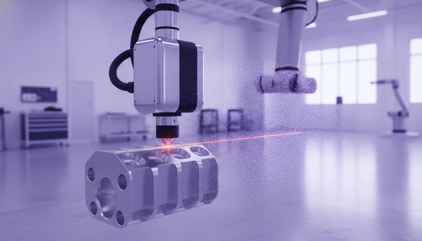
Professional modelling requires a choice between “as-built” and “as-designed” approaches. As-built models capture every imperfection, whilst as-designed models restore the part to its original, idealised state. By applying reverse engineering principles, you can recover lost design documentation and correct historical manufacturing defects. If your project requires this level of industrial precision, our 3D scanning service provides the high-fidelity data needed for a perfect reconstruction.
Ensuring Accuracy and Preparing for UK Manufacturing
The final stage of the reconstruction process is where digital geometry meets physical reality. Mastering how to create a cad model from a scan requires a rigorous validation phase; you’ve got to ensure the new file is fit for the factory floor. Perform a deviation analysis by overlaying your parametric CAD model onto the original high-resolution scan data. This comparison identifies dimensional errors introduced during the modelling phase, ensuring the part adheres to the strict tolerances required for UK industrial applications.
Effective tolerance management is essential when preparing files for a 3D printing service. Different processes, such as FDM or SLS, exhibit varying shrinkage rates and surface finishes. Adjust your CAD geometry to account for these variables. This ensures mating parts fit perfectly upon assembly. In modern product development, where rapid turnaround times define success, these pre-production checks prevent costly reprints and assembly failures. It’s about getting the part right the first time.
Validating Your CAD Model Against the Original Scan
Use “Heat Maps” to visualise the distance between the scan mesh and your new CAD surfaces. Areas highlighted in red or blue indicate where the model deviates from the original part. This visual tool is indispensable for aerospace or military projects where uncompromising accuracy is a legal requirement. Refine specific features until the entire model falls within the specified geometric tolerances of BS 8888:2025.
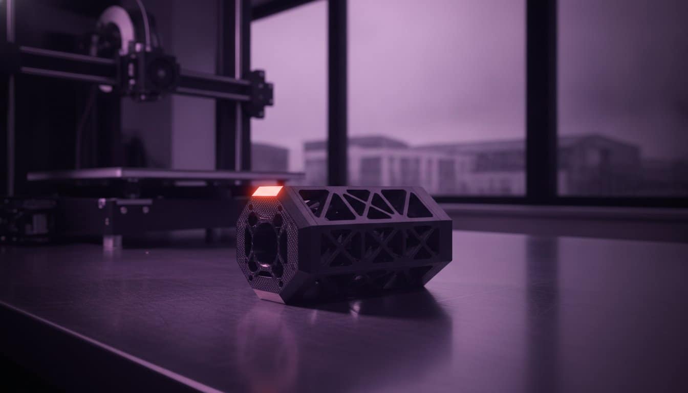
Transitioning from CAD to Rapid Prototyping
A clean, validated CAD model significantly accelerates the rapid prototyping cycle. By eliminating mesh errors and geometry faults at the source, you reduce the time spent in pre-flight software. This precision becomes even more critical when moving into batch production. Consistent geometry ensures the first part off the line is identical to the thousandth, maintaining functional integrity across every unit delivered.
Accelerate Your Production with Manufacture-Ready CAD
The transition from raw scan data to manufacture-ready geometry represents the critical path in modern reverse engineering. By prioritising parametric reconstruction over simple file conversion, you ensure your components meet the rigorous standards of BS 8888:2025. You now understand the professional workflow required to maintain dimensional integrity and design intent. This process eliminates the inaccuracies of “dumb” mesh data and prepares your parts for high-precision batch production.
Mastering how to create a cad model from a scan is a significant competitive advantage in a market that demands both speed and precision. Our studio leverages high-resolution industrial 3D scanning hardware to deliver results that exceed the requirements of the military and aerospace sectors. We specialise in fast turnaround for UK-wide engineering projects, ensuring your deadlines are met without compromising on quality. We’re ready to help you bridge the gap between physical objects and digital blueprints.
Get a professional quote for your Scan-to-CAD project today and transform your physical parts into precise digital assets. Let’s move your project from the scanner to the factory floor with absolute confidence.
Frequently Asked Questions
Can I convert a 3D scan to CAD automatically?
No, fully automatic conversion into manufacture-ready CAD is currently impossible for industrial applications. Whilst “auto-surfacing” tools exist, they create a complex NURBS patch that inherits surface noise and lacks parametric history. This makes the model difficult to edit or use in production. Professional reconstruction involves manual sketching over the mesh data to ensure the final file is clean, precise, and faithful to the original design intent.
What is the best software for creating CAD from a scan?
Geomagic Design X remains the industry standard for professional reverse engineering in 2026. It offers the most robust toolset for extracting features directly from mesh data. QUICKSURFACE 2026 is a strong alternative featuring advanced lofting tools and a live deviation analyser. If you are learning how to create a cad model from a scan, software like SolidWorks 2026 now incorporates AI-driven documentation to streamline the modelling process.
How accurate is a CAD model created from a 3D scan?
Accuracy depends on the combination of metrology-grade hardware and the skill of the modeller. Industrial blue light or laser scanners typically achieve accuracies between 10 and 50 microns. We validate the final results using deviation analysis, which compares the new CAD surfaces directly against the original scan mesh. This process ensures the model meets the strict geometric tolerances required for high-end automotive or aerospace manufacturing.
Do I need a professional 3D scanning service or can I use my phone?
You should choose a professional 3D scanning service if your project requires industrial precision or mechanical assembly. Phone-based LiDAR apps are suitable for visualisations, but they don’t provide the resolution needed for engineering. Metrology-grade hardware captures the crisp edges and fine details that consumer devices miss. This high-fidelity data is essential to ensure your CAD model is built on a reliable and accurate foundation.