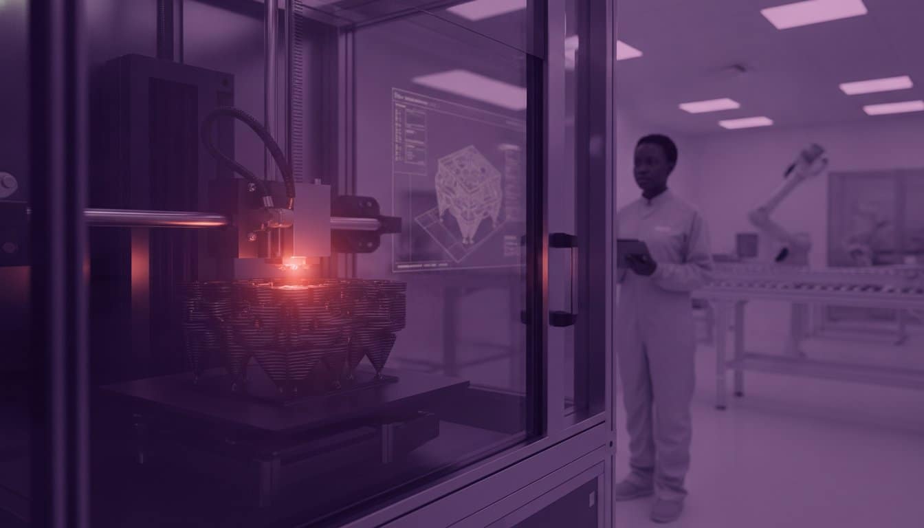
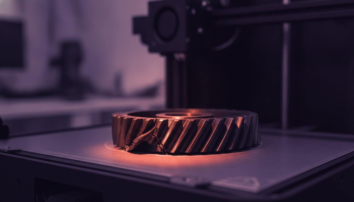
Your CAD model is a masterpiece of precision, yet the physical output often tells a different story. It is a common frustration in the engineering world; a part that meets every digital specification but fails the assembly test due to warping or poor surface quality. You understand that the limitations of fdm 3d printing aren’t just minor inconveniences. They are critical factors that dictate whether a component succeeds in the field or ends up in the scrap bin. Inconsistent mechanical strength and tight-tolerance failures can stall your production timeline and inflate your costs.
This guide provides the technical clarity you need to master Fused Deposition Modelling for industrial applications. We promise to move beyond basic troubleshooting and equip you with professional design strategies that overcome inherent material constraints. You will gain a clear understanding of FDM boundaries, learn specific design rules to prevent common print failures, and receive expert guidance on when to transition your project to SLA or SLS for superior precision. Let’s refine your manufacturing process and deliver the results your clients demand.
Key Takeaways
- Identify how the “stair-step” effect and nozzle diameter dictate the minimum feature size and surface finish of your industrial components.
- Analyse the physics of thermal contraction to proactively mitigate warping and manage support structures for complex geometries.
- Master the technical limitations of fdm 3d printing to ensure every prototype meets strict engineering tolerances and assembly requirements.
- Implement Design for Additive Manufacturing (DfAM) principles to optimise part orientation and align stress loads with the X-Y plane.
- Recognise the critical performance thresholds that signal when to transition from FDM to high-precision SLA or SLS manufacturing processes.
Technical and Aesthetic Constraints: Resolution and Surface Finish
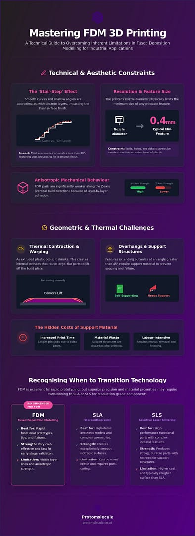
The layer-by-layer nature of the process defines the physical characteristics of every part. The “stair-step” effect occurs because the printer approximates smooth curves with rectangular plastic layers. This is a primary factor in the limitations of fdm 3d printing when aesthetic precision is paramount. Whilst industrial-grade hardware minimises this through finer layer heights, the physics of Fused Deposition Modeling means it is never entirely absent. Nozzle diameter also restricts the X-Y plane resolution; you cannot print a feature thinner than the bead of plastic extruded, typically 0.4mm on standard systems.
Vertical curves and shallow angles suffer most. As the angle of a slope decreases, the horizontal offset between layers increases, making the “steps” more pronounced. This raw finish stands in stark contrast to the isotropic, smooth surfaces produced by SLA or SLS technologies, which often require zero manual intervention to achieve a professional look.
The Challenge of Anisotropic Mechanical Behaviour
Anisotropy is the variation of a material’s physical properties when measured along different axes. In FDM, this manifests as a significant reduction in mechanical strength along the Z-axis. Because parts are built layer-by-layer, the bond between layers is purely thermal. If the previous layer cools too quickly, the subsequent layer won’t fuse perfectly. This makes the vertical axis the most likely point of failure under stress. Industrial rapid prototyping requires careful orientation to ensure load-bearing forces don’t pull these layers apart.
Surface Texture and Post-Processing Requirements
FDM parts possess a distinct tactile roughness that often necessitates secondary operations. To achieve a mirror-like or industrial-grade finish, you must account for post-processing time. Sanding and priming are standard for mechanical parts; chemical smoothing using solvent vapours can melt the outer skin of certain thermoplastics to erase layer lines. Recognising these limitations of fdm 3d printing early allows you to build post-processing into your project timeline effectively.
Geometric and Thermal Challenges in FDM Production
Thermodynamics dictates the success of your print. As extruded plastic transitions from a molten state to a solid one, it contracts. This shrinkage creates internal stresses that manifest as warping, particularly on large flat bases where the cumulative pull of cooling layers overcomes the adhesion to the build plate. This fundamental thermal behaviour remains one of the most persistent limitations of fdm 3d printing in industrial production. You must also account for “elephant’s foot,” where the weight of the part combined with high bed temperatures causes the first few layers to bulge outwards, compromising dimensional accuracy for tight-tolerance assemblies.
Overhangs exceeding 45 degrees require support structures to prevent filament sagging. These aren’t just material sinks; they often degrade the surface quality of the face they touch, requiring significant post-processing. Internal cavities and dense lattice structures present another hurdle. If you design a part with enclosed voids, removing support material becomes physically impossible unless you utilise soluble filaments. Failure to plan for these geometries often results in trapped material that adds unnecessary weight and can interfere with moving parts.
Warping, Shrinkage, and Dimensional Tolerances
Different thermoplastics react uniquely to thermal changes. ABS, whilst offering high impact resistance, has a high shrinkage rate compared to PLA. Professional-grade hardware solves this with heated build chambers. By maintaining an elevated ambient temperature, these machines prevent the rapid cooling that leads to delamination and dimensional drift. Our 3D design service can help you optimise your geometry to account for these material-specific behaviours and ensure your parts meet strict engineering tolerances.
The Cost of Complexity: Support Structures
Support material adds complexity to your project’s bottom line. It increases print duration and generates material waste, impacting both the speed of delivery and the final cost. Whilst breakaway supports are cost-effective for simple geometries, industrial dual-extrusion systems use soluble supports to handle complex internal channels. This allows for geometries that would otherwise be unachievable with standard FDM setups, though it requires longer post-processing times to fully dissolve the auxiliary material.
Strategic Solutions: Designing Around FDM Constraints
Design for Additive Manufacturing (DfAM) transforms technical hurdles into manageable engineering variables. By adopting a DfAM mindset, you bypass the inherent limitations of fdm 3d printing before the first layer even adheres to the build plate. Prioritise part orientation to align your maximum expected stress loads with the X-Y plane. This strategy leverages the superior tensile strength of continuous filament paths rather than relying on the weaker Z-axis layer bonds discussed previously. Incorporating fillets into sharp internal corners also serves a dual purpose; it reduces stress concentrations and provides a stronger anchor to the build plate to resist warping. Utilising professional 3D design services ensures your CAD files are optimised for these specific manufacturing realities.
Industrial FDM vs. Desktop Capabilities
Industrial-grade hardware operates in a different league to desktop alternatives. Whilst home printers struggle with inconsistent ambient temperatures, professional systems use actively heated chambers to maintain dimensional stability. This control is essential when working with high-performance engineering materials like PEEK or Ultem. These materials require specialised extrusion temperatures and precise thermal management that only industrial equipment can provide reliably. Don’t let the failures of entry-level hardware dictate your view of FDM’s industrial potential.
When to Transition to Batch Production
Transitioning to batch production via FDM offers a cost-effective alternative to injection moulding for low-to-medium volumes. It eliminates expensive tooling lead times, though you must account for the slower cycle times inherent to extrusion. This makes it an ideal choice for bridge manufacturing or niche industrial components. Reach out to our team to get a quote and receive a professional assessment of your project’s feasibility. We ensure your design transitions from a digital concept to a high-performance industrial reality without compromise.
Optimise Your Manufacturing Strategy
Success in additive manufacturing depends on your ability to turn technical constraints into design advantages. You now understand that the limitations of fdm 3d printing, from Z-axis anisotropy to thermal warping, are predictable engineering variables rather than insurmountable barriers. By applying rigorous DfAM principles and selecting industrial-grade hardware, you ensure that every prototype or production part meets the uncompromising standards required for high-stakes applications. For projects requiring independent validation of these standards, The Testing Lab PLC provides the accredited assessment necessary to confirm material compliance and structural integrity. Whether you are navigating complex overhangs or managing the shrinkage rates of engineering-grade thermoplastics, professional oversight remains your most valuable asset.
Protomolecule delivers the industrial-grade manufacturing standards necessary for the military and space sectors. We specialise in translating complex CAD models into functional reality with a focus on precision and speed. Contact Protomolecule for professional 3D printing and rapid prototyping solutions to benefit from our specialist expertise and fast turnaround for rapid prototyping. Let’s solve your toughest engineering challenges today and move your project from the screen to the field with absolute confidence.
Frequently Asked Questions
Can FDM 3D printing produce airtight or watertight parts?
Raw FDM prints are rarely airtight or watertight because microscopic gaps exist between the extruded layers. The porous nature of the structure allows liquids and gases to seep through under pressure. To achieve a reliable seal, you must apply secondary post-processing treatments such as epoxy resin coatings or chemical vapour smoothing to fuse the outer skin. Increasing wall thickness and over-extruding the infill can improve resistance but won’t guarantee a hermetic seal without these extra steps. In industrial environments where moisture ingress is a factor, professional resources from Mold Pros Phoenix can assist in evaluating the costs and necessity of mould remediation to ensure a safe workspace.
How do I stop my FDM 3D prints from warping at the corners?
Prevent warping by using a heated build chamber and adding “mouse ears” or large fillets to the corners of your CAD model. Warping is a result of uneven thermal contraction as the plastic cools and pulls away from the build plate. These design modifications increase the surface area in contact with the bed and distribute internal stresses more evenly. These strategies are essential for bypassing the thermal limitations of fdm 3d printing when producing large, flat industrial components.
Is FDM strong enough for functional engineering components?
FDM is highly effective for functional parts if you account for its anisotropic mechanical behaviour during the design phase. Whilst the Z-axis is inherently weaker due to layer adhesion limits, the X-Y plane offers significant tensile strength. Use high-performance engineering materials like carbon-fibre reinforced nylon or PEEK for high-stress applications. Align your primary load paths with the continuous filament strands to ensure the component survives rigorous operational conditions.
What is the minimum wall thickness for a reliable FDM print?
Design your functional parts with a minimum wall thickness of 1.2mm to ensure structural integrity. This dimension allows for three full perimeters when using a standard 0.4mm nozzle, which provides the necessary rigidity for most engineering applications. For components that require high durability or must withstand mechanical fastening, increase this thickness to 2.0mm or more. Walls thinner than 0.8mm are often too fragile to survive post-processing or assembly.
Why does my 3D print have visible lines on the surface?
Visible lines are an inherent characteristic of the extrusion process where rounded beads of plastic are stacked vertically. This “stair-stepping” effect is most prominent on curved surfaces and shallow angles. You can minimise these limitations of fdm 3d printing by reducing the layer height to 0.1mm or using professional sanding and priming techniques. If your project requires a mirror-smooth finish without manual labour, consider transitioning to SLA or SLS technologies.
Can FDM print moving parts in a single assembly?
FDM can produce “print-in-place” moving assemblies such as hinges or linkages within a single build. You must design the assembly with a minimum clearance of 0.3mm to 0.5mm between adjacent surfaces to prevent them from fusing together during the print. This gap allows the parts to remain distinct whilst being captured in the same assembly. Ensure that all internal support material is accessible so it can be removed easily after the print is complete.