
An FDM print is only as strong as its weakest layer, and most engineering failures happen long before the nozzle even heats up. You’ve likely faced the frustration of a 20-hour print failing due to poor layer adhesion or found that inaccurate tolerances have rendered a complex assembly useless. These issues don’t just waste material; they compromise your project deadlines and inflate production costs. Designing parts for fdm printing requires a fundamental shift from traditional subtractive mindsets to a focus on additive-specific constraints.
We recognise that your project deadlines are non-negotiable. This guide provides the technical expertise you need to master the essential design rules for high-performance FDM 3D printing and rapid production. You’ll learn how to create robust, functional prototypes that withstand industrial testing whilst reducing lead times through minimal support structures. We’ll cover everything from optimal wall thicknesses and orientation strategies to the geometric tweaks that ensure repeatable results in batch production. Follow these principles to turn your CAD models into high-precision components with total confidence.
Key Takeaways
- Account for anisotropy by aligning tensile loads with the X-Y plane to ensure your components withstand industrial-grade stresses and mechanical testing.
- Apply the 45-degree rule to your CAD models to produce self-supporting angles, significantly reducing lead times and material waste.
- Master precision tolerances when designing parts for fdm printing to ensure perfect assembly fits whilst avoiding common defects like “elephant’s foot”.
- Accelerate your workflow by utilising 3D nesting strategies that maximise build plate efficiency for rapid prototyping and high-volume batch production.
Mastering FDM Geometry: Orientation and Structural Integrity
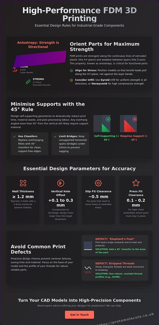
Success in designing parts for fdm printing starts with acknowledging that additive manufacturing is not isotropic. Unlike injection moulding or CNC machining, Fused filament fabrication (FFF) creates components by stacking layers, making the bond between those layers the most likely point of failure. You must orient your CAD models so that tensile loads pull along the continuous extruded strands of the X-Y plane rather than trying to peel the layers apart along the vertical Z-axis. This strategic alignment is the difference between a functional industrial component and a part that snaps under its first load.
When you use reverse engineering to replace legacy components, this orientation becomes even more critical. Original cast or forged parts often have uniform strength, but your 3D printed replacement must be redesigned to account for the specific mechanical stresses of the machinery. By scanning the original part and analysing its wear patterns, you can optimise the geometry to ensure the internal “grain” of the print reinforces the areas of highest stress. Layer height also plays a vital role here; whilst thinner layers improve aesthetic finish, they also reduce the “stair-stepping” effect on curved surfaces, which can act as stress concentrators if not managed correctly.
Designing for Layer Adhesion and Strength
Anisotropy is the directional dependence of a material’s mechanical properties. To mitigate its effects, select infill patterns that provide multi-directional support. Whilst honeycomb patterns offer excellent compressive strength, gyroid infill provides more uniform strength in all directions and prevents trapped gasses during high-speed printing. Focus on wall thickness to improve torsional rigidity; adding extra perimeters is often more effective than simply increasing infill density.
Wall Thickness and Shell Optimisation
A minimum wall thickness of 1.2mm serves as the industrial baseline for vertical stability. This dimension typically represents three shells when using a standard 0.4mm nozzle, providing enough structural mass to prevent buckling. Balancing your shell count with infill density allows you to accelerate production cycles. By prioritising shell count, you maintain structural integrity whilst reducing the time the print head spends on complex internal infill paths, effectively lowering the overall part weight without sacrificing performance.
Essential Design Rules for FDM Accuracy and Tolerance
Accuracy in FDM isn’t a given; it’s engineered. When designing parts for fdm printing, you must navigate the physical limitations of molten thermoplastic. The 45-degree rule is your primary tool for efficiency. Any angle steeper than 45 degrees relative to the build plate requires support material, which increases both print time and post-processing labour. To avoid the common “elephant’s foot” defect where the first few layers expand outwards, add a small 45-degree chamfer to the base of your part. This ensures your dimensions remain true from the first layer to the last.
Hole shrinkage is another industrial reality. As the plastic cools and contracts, internal diameters often finish 0.1mm to 0.3mm smaller than your CAD dimensions. Don’t waste time on reprints; design your vertical axis holes with this offset built-in. If your geometry is particularly complex, our 3D design services can help refine these tolerances before you commit to a full production run. This proactive approach saves time and ensures your components function exactly as intended.
Overhangs, Bridges, and Support Minimisation
Replace fillets with chamfers on overhanging edges. A fillet starts at a 0-degree angle, which guarantees failure without supports. A chamfer maintains a constant, self-supporting slope. For horizontal gaps, FDM nozzles can reliably “bridge” across open air, but keep these spans under 10mm to avoid sagging. If a model is too complex for these rules, consider splitting it into multiple components. You can then join them post-print to eliminate support material entirely and improve the surface finish of each section.
Tolerances for Interlocking and Mating Parts
Industrial assemblies require precise clearances. For a reliable “slip fit” where parts move freely, design a 0.5mm gap between mating surfaces. If you need a “press fit” that stays in place, reduce that clearance to between 0.1mm and 0.2mm. When adding threads to your design, avoid sharp triangular profiles. Rounded ACME threads are far more robust for 3D printing, as they reduce stress concentrations and are less prone to stripping. If you need assistance with these technical specifications, feel free to get in touch for expert advice on your next project.
Strategic Design for Rapid Prototyping and Batch Production
Optimising for the end of the production line is just as vital as the initial CAD sketch. When designing parts for fdm printing, you must plan for post-processing before the first layer is even deposited. Place support contact points on internal or non-critical surfaces to preserve the cosmetic finish of visible faces. Material choice also dictates your design approach. Whilst PLA is ideal for rapid functional testing, end-use industrial components require high-performance materials like ASA for UV resistance or Carbon Fibre PETG for superior stiffness. Matching the material to the environment ensures your part doesn’t just look the part but survives it.
Scaling from a single unit to a full production run requires a shift in logic. Utilise a professional 3D printing service to handle the complexities of 3D nesting. By stacking and interlocking parts within the build volume, you maximise machine efficiency and slash lead times. This strategic arrangement turns a desktop-level process into a viable batch production service capable of delivering hundreds of units with consistent quality and reduced machine time.
Accelerating the Prototyping Cycle
Speed is the primary currency of modern product development. You can reduce print time by up to 30% by simplifying internal geometry that doesn’t impact structural requirements. Identify non-critical features, such as aesthetic fillets on internal ribs or overly complex branding, and remove them to streamline the toolpath. These small CAD adjustments allow for faster iterations, letting you fail fast and succeed sooner.
Design for Batch Repeatability
Consistency is the benchmark of industrial manufacturing. Standardise feature sizes across your part family to ensure uniform cooling and prevent warping caused by uneven thermal contraction. For tall, thin components, incorporate sacrificial stabilising structures into your CAD. These anchors prevent vibration during high-speed printing, ensuring every part in a batch meets your uncompromising standards. For projects requiring immediate turnaround, our rapid prototyping workflow ensures your designs move from screen to hand without delay.
Accelerate Your Production with Precision Engineering
Mastering the technical constraints of designing parts for fdm printing is the only way to ensure your components perform under industrial stress. You’ve seen how strategic orientation overcomes anisotropy and how precise tolerance adjustments prevent assembly failures. By applying these DfAM principles, you move beyond simple prototypes to create robust, end-use parts that meet the rigorous standards of the military, space, and commercial sectors.
We don’t just print parts; we solve complex manufacturing challenges with industrial-grade precision. Our specialist studio is built for speed and reliability, delivering the rapid turnaround times your project deadlines demand. Whether you’re scaling a single prototype or launching a full batch production run, we have the expertise to deliver repeatable results. Get an instant quote for your FDM project today and start your journey toward high-performance additive manufacturing. Your next engineering breakthrough is just a build plate away.
Frequently Asked Questions
What is the minimum wall thickness for FDM printed parts?
The absolute minimum wall thickness for non-structural FDM components is 0.8mm, which equates to two passes of a standard 0.4mm nozzle. For load-bearing industrial parts, increase this to at least 1.2mm or 1.6mm to ensure vertical stability and impact resistance. Designing parts for fdm printing with walls thinner than 0.8mm often leads to delamination or fragile shells that cannot withstand standard handling.
How do I avoid using support structures in my FDM design?
Eliminate support structures by applying the 45-degree rule to all overhangs and using “tear-drop” profiles for horizontal holes. These geometric tweaks allow the printer to build upon previous layers without needing external scaffolding. You can also design self-supporting bridges for gaps under 10mm. This approach reduces material waste and slashes post-processing time, directly accelerating your production cycle.
Why do holes in 3D printed parts always turn out smaller than my CAD model?
Holes appear smaller because thermoplastic contracts as it cools and the slicer approximates circles as a series of straight-line segments. This inward pull, combined with the way the nozzle deposits material on internal curves, reduces the finished diameter. Compensate by designing internal diameters 0.1mm to 0.3mm larger in your CAD software. Always print a small test coupon to verify the exact shrinkage for your specific material and printer configuration.
Can FDM printed parts be made airtight or watertight?
FDM parts are not inherently watertight due to the microscopic gaps between layers and infill paths. To achieve a reliable seal, increase your perimeter count to at least four or five and use a slightly higher extrusion multiplier to force layers together. For high-pressure applications, apply a post-print sealant or epoxy resin to the surface. This closes the internal porosity and ensures the component remains functional in fluid-handling environments.
What is the best orientation for strength in FDM printing?
Orient your part so that the primary tensile loads align with the X-Y plane of the print bed. This ensures the continuous extruded strands of plastic take the stress, rather than the weaker bonds between layers. If a part faces complex multi-axial loads, consider splitting the model into multiple components and joining them post-print. This allows you to optimise the “grain” direction for each section, ensuring maximum durability across the entire assembly.
How much clearance should I leave between mating parts in an assembly?
Use a clearance of 0.5mm for free-moving slip fits and 0.1mm to 0.2mm for interference or press fits. These values account for the standard dimensional variations found when designing parts for fdm printing. If you’re working with complex assemblies, always factor in tolerance stack-up across multiple components. Conduct a test print of the mating sections to verify the fit before committing to a full batch production run.