What if the primary cause of your part’s failure isn’t the material choice, but the direction it was printed? You have likely experienced the frustration of a functional component snapping cleanly along a layer line during a stress test. It is a common engineering headache that leads to wasted material and missed deadlines. Mastering fdm print orientation for strength is the only way to move past these unpredictable mechanical failures and secure reliable results.
We understand that your project’s success depends on parts that perform exactly as designed. This guide provides the technical expertise to help you navigate anisotropic properties and align load paths with precision. You will learn to optimise your designs for our rapid prototyping and batch production services, ensuring every component meets industrial standards. We will explore how to leverage 2026 high-speed printing architectures and advanced slicer settings to achieve predictable durability. By the end of this article, you will have the strategies needed to reduce failure rates and deliver high-performance parts that withstand the most demanding functional testing.
Key Takeaways
- Understand the physics of anisotropy to identify why inter-layer bonding is the most frequent point of failure in functional components.
- Apply the Golden Rule of load alignment by positioning continuous filament strands parallel to the direction of highest mechanical stress.
- Master the core principles of fdm print orientation for strength to prevent parts from snapping along layer lines under tension.
- Optimise your 3D design workflow to create geometries that naturally dictate their own strongest print orientation.
- Transition from standard settings to industrial-grade results by integrating professional batch production strategies for consistent durability across every unit.
The Physics of Anisotropy: Why FDM Print Orientation Dictates Strength
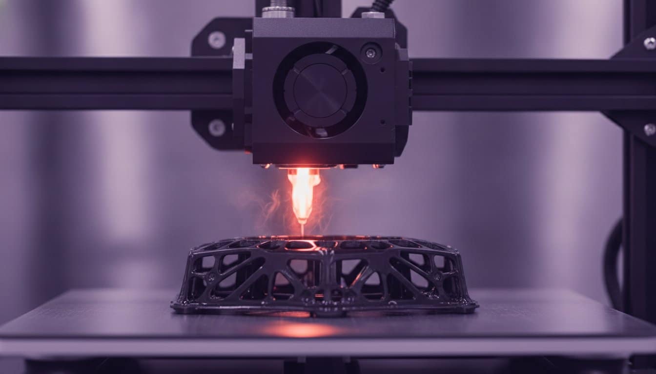
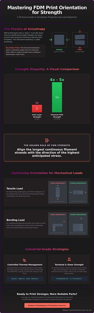
FDM parts are not uniform solids. Unlike injection-moulded components that exhibit isotropic properties, 3D printed parts are fundamentally directional. Understanding The Physics of Anisotropy is essential for any engineer looking to master fdm print orientation for strength. In practical terms, anisotropy describes how a material’s mechanical behaviour changes depending on the direction of the applied load. When you extrude thermoplastic through a nozzle, you create a structure that’s significantly stronger along the path of the filament than it is between the stacked layers.
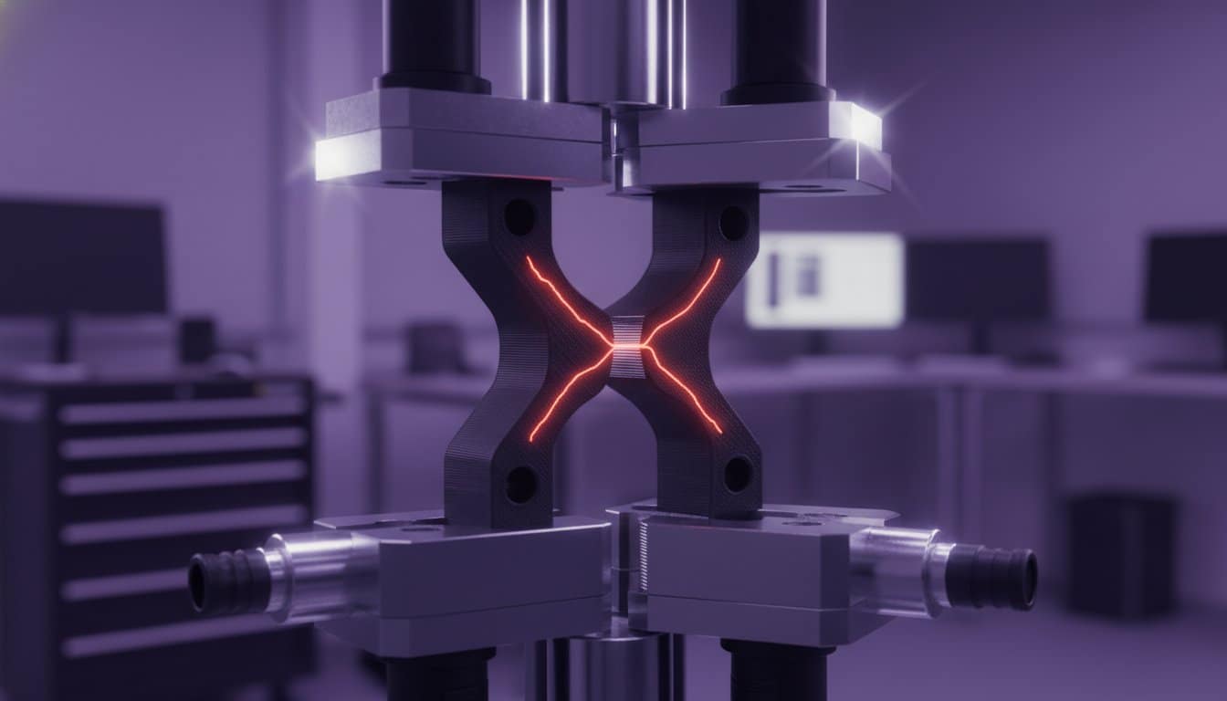
Think of FDM printing like wood grain. A piece of timber is incredibly difficult to snap across the grain but splits easily along it. Your 3D printed part behaves the same way. Within a single extruded strand, polymer chains are tightly entwined through molecular fusion. However, the bond between layers relies on thermal adhesion, which is inherently weaker. This creates the “Z-axis weakness” that causes parts to delaminate or snap when stressed perpendicular to the print bed. You must account for this directional bias during the design phase to avoid catastrophic failure.
The Role of Thermal Management in Layer Adhesion
Successful layer bonding depends on how well the new molten plastic “knits” with the previous layer. Ambient temperature and cooling rates dictate this process. If the previous layer cools too quickly, the polymer chains cannot intermingle effectively, leading to poor adhesion. This is why our industrial 3D printing service utilises controlled thermal environments. These machines maintain high chamber temperatures to slow cooling, achieving superior Z-axis strength compared to desktop alternatives that lack heated enclosures.
Tensile Strength vs. Interlaminar Shear
Engineers must distinguish between tensile strength and interlaminar shear. Tensile strength in the XY plane is typically 4 to 5 times higher than in the Z-axis because the load is supported by the continuous filament strands. Conversely, interlaminar shear stress targets the boundaries between layers. If your design subjects these boundaries to high stress, the part will fail prematurely. You must align your load vectors to ensure tension runs parallel to the filament paths, never across them.
Optimising Orientation for Specific Mechanical Loads
Before you open your slicing software, you must map the primary load vectors of your component. The Golden Rule for fdm print orientation for strength is simple: align the longest continuous filament strands with the direction of the highest stress. This ensures the load is carried by the molecular bonds within the plastic strand rather than the weaker adhesive bonds between layers. Failing to plan this directional alignment often results in parts that look perfect but fail instantly under operational stress.
You will often face a trade-off between peak mechanical performance and the volume of support material required. Whilst orienting a part at a 45-degree angle might improve surface finish, it often introduces complex shear planes that compromise structural integrity. Prioritise strength by ensuring critical features, such as holes and bores, are printed with their axes vertical to the build plate. This maintains perfect circularity and places the strongest perimeters exactly where they are needed to resist radial forces. If your geometry is complex, our 3D design service can help refine the model for the best possible manufacturing outcome.
Handling Tensile and Bending Forces
When designing brackets or levers, orient the part so that bending forces do not “peel” the layers apart. For a cantilever beam under vertical load, the optimal orientation is to print the beam flat on its side so the filament runs the full length of the span. If a vertical column faces side-loading, print it horizontally; a vertical print would snap at the base because the stress acts directly on the interlaminar boundaries. Use the following logic for common loads:
- Tensile loads: Align parallel to the filament path.
- Compressive loads: Align perpendicular to layers to maximise surface area contact.
- Shear loads: Offset the orientation to ensure the shear plane does not align with layer lines.
Designing for Torsional and Shear Stress
Shafts and gears require a specific approach to prevent rotational shearing. Increase your wall thickness (shells) rather than relying on infill, as perimeters contribute significantly more to torsional rigidity. For high-torque applications, we recommend at least 4 to 6 perimeters to ensure the outer skin can handle the stress. When dealing with shear loads, orient the part so the layers are “stacked” against the force, forcing the load to cross multiple filament strands rather than sliding between two layers.
Professional Strategies for Industrial-Grade FDM Parts
Relying on slicer defaults is a recipe for failure in high-stakes engineering. When you move to batch production, you must treat orientation as a fixed specification, not a suggestion. Professional-grade results require a deep synergy between 3D design and manufacturing. By designing geometries that dictate a single logical print direction, you eliminate operator error and guarantee fdm print orientation for strength across every unit. Smart design choices, such as integrated self-supporting angles, ensure the part is always printed in its strongest possible state.
Post-processing techniques like annealing can sometimes mitigate Z-axis weaknesses by promoting polymer chain diffusion across layer boundaries. However, these methods often introduce dimensional shrinkage or warping. They’re a secondary reinforcement, not a cure for poor orientation. For complex, high-stakes components, partnering with a professional studio ensures these variables are managed with industrial precision. We prioritise structural integrity from the first layer to the last.
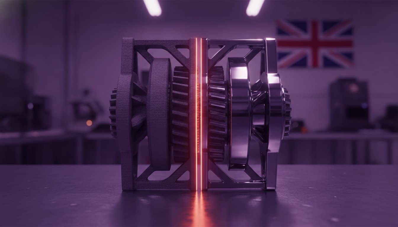
Validation and Destructive Testing
FEA data provides a theoretical baseline, but real-world loads often find hidden stress concentrations that software might overlook. We recommend printing test coupons in multiple orientations to validate your simulations against physical reality. Our rapid prototyping workflow allows us to perform destructive testing on early iterations. This rigorous approach ensures the final part exceeds safety margins before you commit to full-scale manufacturing.
Scaling from Prototype to Production
Scaling from one part to one hundred introduces the challenge of bed packing efficiency. Whilst it’s tempting to rotate parts to fit more on a single build plate, this often compromises structural integrity. Our 3D printing service prioritises part performance over packing density. We lock in specialised orientation protocols for every project, ensuring the first part is just as resilient as the five-hundredth. This consistency separates industrial manufacturing from hobbyist-level output.
Deploy High-Performance FDM Components
Mastering the directional nature of additive manufacturing is what separates functional prototypes from end-use failures. You now understand that anisotropy is an engineering variable to be managed rather than a limitation to be feared. By aligning load vectors with continuous filament paths and validating designs through physical testing, you ensure your components withstand real-world stress. High-stakes projects require this level of precision; fdm print orientation for strength is the foundation of that reliability.
Our team brings extensive experience from the space and military sectors to every project, providing ISO-standard material data sheets to back up our technical claims. We offer a rapid turnaround on industrial-grade FDM components, ensuring your project remains on schedule without compromising on structural integrity. Trust our expertise to deliver parts that perform exactly as intended, every single time. We are ready to help you solve your most complex manufacturing challenges.
Get an expert technical review and quote for your high-strength parts and start your next production run with total confidence.
Frequently Asked Questions
Is 100% infill better for strength than changing the print orientation?
No, increasing infill to 100% cannot compensate for poor part orientation. Whilst a solid part has higher compressive strength, it remains fundamentally anisotropic and will still fail if the load acts perpendicular to the layer lines. You’ll achieve better results by aligning the filament path with the stress vector at 40% to 60% infill than by printing a solid part in the wrong direction. Prioritise load path alignment to ensure your material works efficiently.
How does layer height affect the overall strength of an FDM part?
Thicker layers generally produce stronger parts because they possess more thermal mass, which leads to better fusion between the extruded strands. However, this creates a trade-off with dimensional accuracy and surface quality. For most functional engineering components, a layer height between 0.2mm and 0.3mm provides the best balance between structural integrity and precision. Avoid extremely thin layers for load-bearing parts, as the increased number of interfaces creates more potential failure points.
Can I use support material to print a part in a stronger orientation?
Yes, using support material is a vital strategy to achieve the best fdm print orientation for strength. Although supports increase material waste and post-processing time, the structural advantage of aligning your filament perimeters with the primary load path is far more important. This approach is essential for complex geometries like cantilever brackets, where the strongest orientation often requires the part to be suspended or angled off the build plate.
What is the strongest 3D printing material for FDM when orientation is optimised?
Carbon Fiber Nylon (PA12 CF) is the strongest widely available material for industrial FDM, reaching tensile strengths of up to 70 MPa when correctly oriented. This composite material excels when the load runs parallel to the carbon fibres within the filament strands. For extreme thermal or chemical environments, high-performance polymers such as PEEK or PEKK offer even higher mechanical properties. Always match your material choice to the specific environmental demands of your application.